Disassembling a Leg

This guide shows how to disassemble a leg until the motors have no load (useful for encoder calibration).

Tools Needed

  • A screwdriver compatible with the hex-head screws

  • Allen keys

  • 9/32” socket and wrench - Optional: 1/2” socket for step 2

Note

When reassembling, read the last step carefully.

Instructions

  1. Reference the “How-To take off a leg” guide to reach the point where the leg is removed from the robot.

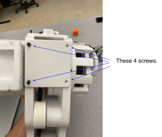
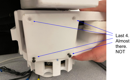
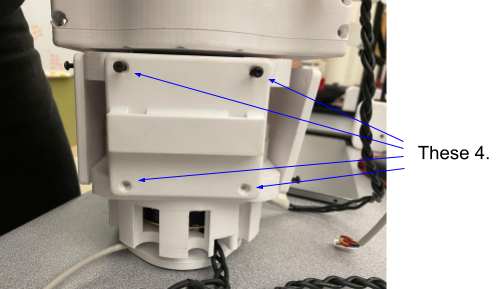
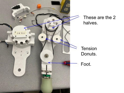
  2. Remove the two screws holding the two halves together. On the same side, remove the two screws that hold the tension donuts in place (four screws total).

    screws holding halves and tension donuts

    Figure 1.

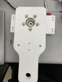
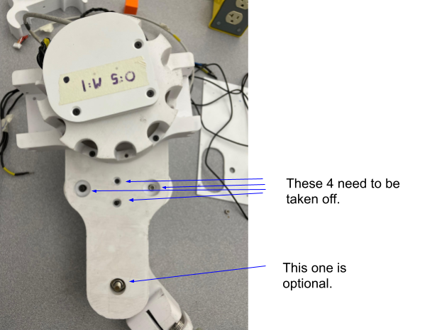
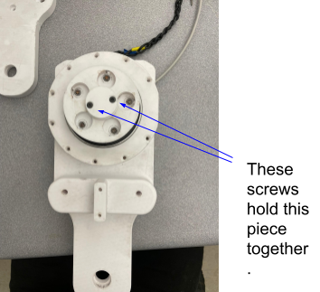
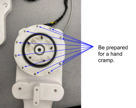
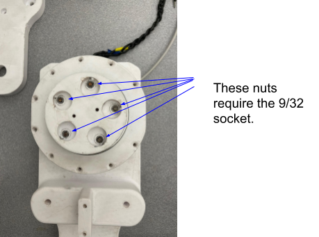
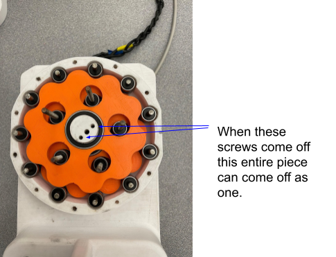
  3. Remove the three plates at the top of the leg (each plate has four screws). The location of the plates is shown in Figures 2, 3, and 4. The order of removal does not matter.

    top plate 1

    Figure 2.

    top plate 2

    Figure 3.

    top plate 3

    Figure 4.

  4. With the plates removed, take off the two halves. The two tension donuts and the foot should come off with the halves; see Figure 5. For the remaining steps we will examine the right half (the foot motor half).

    right half with foot and donuts

    Figure 5.

  5. On the foot-controlling half, remove the spacers held by two screws (Figure 6).

    spacers held by screws

    Figure 6.

  6. Remove the part that holds the belt by taking off the five nuts that secure it (Figure 7).

    belt holder nuts

    Figure 7.

  7. Remove the ten screws holding the top plate to the bottom (Figure 8).

    top plate screws

    Figure 8.

  8. After removing the plate you will see the cycloidal drive assembly. Use the correct Allen key to remove the cap (Figure 9).

    cycloidal drive cap

    Figure 9.

  9. Remove the two screws that hold the bearing and gear in place, then remove the top gear (Figure 10).

    top gear removal

    Figure 10.

  10. Remove the two screws for the second gear as shown in Figure 11.

second gear screws

Figure 11.

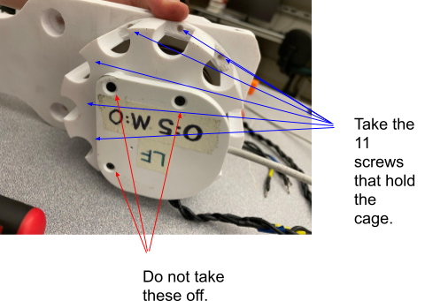
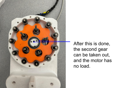
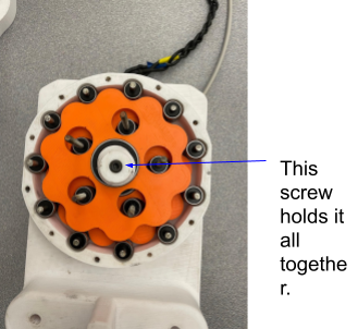
  1. To remove the motor cage: you can reinstall the large cap taken off in step 7 to help prevent bearings from falling out. Alternatively, remove the cage before step 7 if needed by taking off the eleven screws on the back (Figure 12). Do not remove the encoder plate unless you intend to reinitialize encoders.

motor cage back screws

Figure 12.

Warning

Do not remove the encoder plate unless you will reinitialize the encoders; removing it will require encoder reinitialization.

  1. Repeat steps 6–11 for the other half (shoulder control). The difference is a leg plate instead of the belt-holder piece (Figure 13).

second half / shoulder

Figure 13.

  1. To fully disassemble, repeat steps 6–11 as needed for all subassemblies.

  2. To reassemble, follow the steps in reverse order. Hand-tighten all bolts/screws (including when using a socket; hold the socket by hand). Overtightening can crack plastics and cause damage.