Pinouts and Hardware
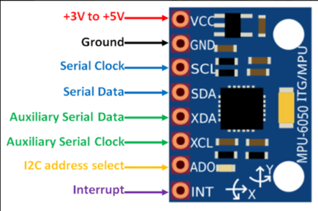
IMU
The RamBOT primary functions are controlled through two core microcontrollers and an Internal Measurement Unit. (IMU)
Teensy 4.1
The Teensy 4.1 microcontroller is the RamBOTs core motion controller, communicating with the ODrives and motor encoders and utilizing the IMU for balance during operation.
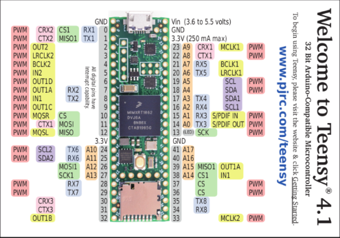
Pinout Tables
Here is a full pinout of how our Teensy 4.1 communicates with the ODrives & IMU to control motion on the RamBOT:
Teensy |
IMU |
O-Drive (#) |
Teensy UART |
O-Drive PIN |
LEDs |
|---|---|---|---|---|---|
0 |
1 |
RX |
2 |
||
1 |
1 |
TX |
1 |
||
2 |
LED |
||||
3 |
LED |
||||
4 |
LED |
||||
5 |
LED |
||||
6 |
LED |
||||
7 |
2 |
RX |
2 |
||
8 |
2 |
TX |
1 |
||
9 |
|||||
10 |
|||||
11 |
|||||
12 |
|||||
13 |
|||||
14 |
3 |
TX |
1 |
||
15 |
3 |
RX |
2 |
||
16 |
4 |
RX |
2 |
||
17 |
4 |
TX |
1 |
||
18 |
SDA |
||||
19 |
SCL |
||||
20 |
5 |
TX |
1 |
||
21 |
5 |
RX |
2 |
||
22 |
|||||
23 |
|||||
24 |
6 |
RX |
2 |
||
25 |
6 |
TX |
1 |
||
3V-L |
VCC |
||||
3V-R |
|||||
5V |
|||||
GND |
GND |
GND |
GND |
Here is a full pinout of how our Odrives and Odrive daughterboards communicate with the motor encoders:
Pin Number |
ODrive Pin Name |
Encoder Pin |
Encoder 0/1 |
|---|---|---|---|
1 |
3v3 |
5 |
0 & 1 |
2 |
GND |
GND |
0 & 1 |
3 |
CAN H |
||
4 |
CAN L |
||
5 |
GND |
GND |
0 & 1 |
6 |
AVCC |
||
7 |
AGND |
||
8 |
SCK |
4 |
0 & 1 |
9 |
MISO |
2 |
0 & 1 |
10 |
MOSI |
1 |
0 & 1 |
11 |
1 |
||
12 |
2 |
||
13 |
3 |
||
14 |
4 |
||
15 |
5 |
||
16 |
6 |
||
17 |
7 |
3 |
0 |
18 |
8 |
3 |
1 |
19 |
GND |
GND |
0 & 1 |
20 |
GND |
GND |
0 & 1 |
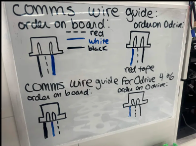
Communication Wires
For successful communication between all hardware components, there are specific wiring diagrams to follow when creating our custom cabling on the RamBOT. The primary cable structure is made up of shielded custom-made JST-XH cables.
Here is a hand-drawn guide to correctly wire the communication wires from the Teensy to the ODrives: